I am making all the schematics and taking pics of all the hardware. I am also videoing all the progress.
Next thing I will be doing is simulating all the schematics before I build the more complex parts.
Thursday, March 29, 2012
Just trying to get my blog out there
{EAV:a0afc2bea14f8c11}
So I want to draw as many people to my blog as I can. Why you may ask? I want to be able to get comments that will help me better understand the people who would want to buy a DIY computer and help educate people the easy and fun way
So I want to draw as many people to my blog as I can. Why you may ask? I want to be able to get comments that will help me better understand the people who would want to buy a DIY computer and help educate people the easy and fun way
Thursday, March 22, 2012
The memory map
Activity 34
Creating the memory map was a little
confusing because the output switching but after a little trial and
error and studying the memory map in the book and arranging the chips
in the order of the book I got them all to work. Now I need to figure
out how to make my own keyboard and video on my own and implement
them. I do have a book on creating my own video game console so I am
going to combined that with what I have and it should lead me in the
right direction.
Tuesday, March 20, 2012
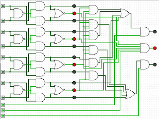
Update on the 4bit ripple comparator
After looking at more info on the comparator I decided to create a 1bit comparator in Logisim. (http://ozark.hendrix.edu/~burch/logisim/)
It came out great because then I found the equation for the comparator and used it to make the 1bit into a 4bit ripple comparator. Here is how it is.
.jpg)
It came out great because then I found the equation for the comparator and used it to make the 1bit into a 4bit ripple comparator. Here is how it is.
.jpg)
The inputs are always true or on tell it is attached to another one. I am not 100% that this is the best way to do it. Let me know if there is a batter way
Monday, March 19, 2012
Logic design software
A few logic design software's.
WinLogiLab
http://www.griffith.edu.au/professional-page/charles-hacker/resources/winlogilab
The logic lab
http://www.neuroproductions.be/logic-lab/
Simple solver
http://home.roadrunner.com/~ssolver/syn.html
Logisim
http://ozark.hendrix.edu/~burch/logisim/
I am going to try a few out and see which one works best for me and see if it cant speed up creating some of these more elaborate logic deign
Here is a list of more but not all of them are free.
http://www.electronicsoft.net/en-us/dept_3.html
Set less than or SLT
To be more MIPS compatible I need the function STL. After a lot of research and some help from cadet1620 I found from a book that I had called "Fundamentals of Logic Design 4th edition by Charles H. Roth, Jr." that STL is part of a set called a Comparator. Also I found it on this web site http://www.electronics-tutorials.ws/combination/comb_8.html. The logic set does not match exactly between the two so I am going to have to figure out exactly how it works so I can add it to my ALU. Also I might have to add my functions to the CPU emulator to incorporate my additions. More to come as I figure it out more clearly.
After looking closer I found that it is called Digital magnitude comparators. The IC that goes with it is a TTL 7 485. The logic diagram helped me understand what was need to cascade 4bit comparators. I found the info here http://www.dauniv.ac.in/downloads/Digitalsystems_PPTs/DigDesignCh12L1.pdf
After looking closer I found that it is called Digital magnitude comparators. The IC that goes with it is a TTL 7 485. The logic diagram helped me understand what was need to cascade 4bit comparators. I found the info here http://www.dauniv.ac.in/downloads/Digitalsystems_PPTs/DigDesignCh12L1.pdf
Sunday, March 18, 2012
Using the software
i went though the Assembler simulator and the CPU simulator and they worked like expect. I tried out all the samples and they worked great. Note I really like how the assembler simulator translate the assembly to binary now there should be one for windows it would be really cool to see the binary code that runs a basic exe file.
Update to my 16bit Adder
So with a few additions to my 4bit adder with look ahead carry I believe I can now detect over flow situations. I have not tested it 100% but I did do a few test and it worked every time
Check it..
OUT out[4],carry,OvF; //added OvF as an out pin
then added
Or(a=cout12,b=cout13,out=c1,out=carry);
Xor(a=out42,b=c1,out=OvF); for the over flow detection
Now just to add it to my ALU
8bit adder
Add4(a=a[0..3],b=b[0..3],c=c,out=out[0..3],carry=carry1,OvF=OvF1);//ignore overflow in first set
Add4(a=a[4..7],b=b[4..7],c=carry1,out=out[4..7],carry=carry,OvF=OvF);
16bit adder
Add8(a=a[0..7],b=b[0..7],c=false,out=out[0..7],carry=carry1,OvF=OvF1);//ignore overflow here
Add8(a=a[8..15],b=b[8..15],c=carry1,out=out[8..15],carry=carry,OvF=OvF);//out put here
First step to optimize ALU
I found a good schematic for look ahead carry adder 4 bit and added it to my 4bit adder. But before I did that I was thinking why would adding more gates make it go any faster then I thought the adding part the less gates it acutely goes through the faster and since the carry is just essentially copying the input and working on it in parallel of the actually addition I can see how it could be a lot faster. With no further ado here is the code I got from the schematic.
[code]
CHIP Add4 {
IN a[4], b[4],c;
OUT out[4],carry;
PARTS:
This is my first 4bit adder
/* HalfAdder(a=a[0],b=b[0], sum=out[0], carry=c1);
FullAdder(a=c1,b=a[1],c=b[1],sum=out[1],carry=outa3);
FullAdder(a=outa3,b=a[2],c=b[2],sum=out[2],carry=outa4);
FullAdder(a=outa4,b=a[3],c=b[3],sum=out[3],carry=outa5);*/
//A0 B0
And(a=a[0],b=b[0],out=out1);
Or(a=a[0],b=b[0],out=out2);
And(a=out2,b=c,out=out3);//needs an input
Or(a=out1,b=out3,out=out4);
Not(in=out2,out=out5);
Or(a=out5,b=out1,out=out6);
Xor(a=out6,b=c,out=out7);//needs an input
Not(in=out7,out=out[0]);
//A1 B1
And(a=a[1],b=b[1],out=out11);
Or(a=a[1],b=b[1],out=out21);
And(a=out21,b=out4,out=out31);//needs an input
Or(a=out31,b=out11,out=out41);
Not(in=out21,out=out51);
Or(a=out51,b=out11,out=out61);
Xor(a=out61,b=out4,out=out71);//needs an input
Not(in=out71,out=out[1]);
//A2 B2
And(a=a[2],b=b[2],out=out12);
Or(a=a[2],b=b[2],out=out22);
And(a=out22,b=out41,out=out32);//needs an input
Or(a=out32,b=out12,out=out42);
Not(in=out22,out=out52);
Or(a=out52,b=out12,out=out62);
Xor(a=out62,b=out41,out=out72);//needs an input
Not(in=out72,out=out[2]);
//A3 B3
And(a=a[3],b=b[3],out=out13);
Or(a=a[3],b=b[3],out=out23);
//And(a=out2,b=,out=out3);//needs an input
//Or(a=out3,b=b[0],out=out4);
Not(in=out23,out=out53);
Or(a=out53,b=out13,out=out63);
Xor(a=out63,b=out42,out=out73);//needs an input
Not(in=out73,out=out[3]);
//C1
//4 way and
And(a=out1,b=out21,out=cout1);
And(a=cout1,b=out22,out=cout2);
And(a=cout2,b=out23,out=cout3);//out
//3 way and
And(a=out11,b=out22,out=cout4);
And(a=cout4,b=out23,out=cout5);//out
//
And(a=out12,b=out23,out=cout6);//out
//4 way and
And(a=out2,b=out21,out=cout7);
And(a=cout7,b=out22,out=cout8);
And(a=cout8,b=out23,out=cout9);//out
//4 way or
Or(a=cout3,b=cout5,out=cout10);
Or(a=cout10,b=cout6,out=cout11);
Or(a=cout11,b=cout13,out=cout12);//out
And(a=cout9,b=c,out=cout13);
Or(a=cout12,b=cout13,out=carry);
}
[/code]
If any one knows how I can break this up into basic adder and faster carry sections let me know. I haven't annualized the code that close to see what would need to be done.
The more help I get the faster I can get all of this done and have a open source system that any one could build.
Saturday, March 17, 2012
Update
Update 4
Creation of all Logic gates with NAND IC 4011 CMOS
|
Gate types
|
Done
|
|
AND
|
X
|
|
OR
|
X
|
|
NOR
|
X
|
|
NAnd
|
X
|
|
NOT
|
X
|
|
XOR
|
|
|
XNOR
|
|
They are all done now moving on to composite gates
Update on the Switch to CPU Kits
Update 3
Creation of all Logic gates with transistors
|
Gate types
|
Done
|
|
AND
|
X
|
|
OR
|
X
|
|
NOR
|
X
|
|
NAnd
|
X
|
|
NOT
|
X
|
|
XOR
|
|
|
XNOR
|
|
Again the exclusive gates seem to have more components then
any others. I will try them after I complete the IC gates.
Friday, March 16, 2012
A further update on Switches to cpu's
Update on step one create all basic logic gates with
switches
So far I have made
|
Gate types
|
Done
|
|
AND
|
X
|
|
OR
|
X
|
|
NOR
|
X
|
|
NAnd
|
X
|
|
NOT
|
X
|
|
XOR
|
|
|
XNOR
|
|
Unable to make the Exclusive gates right now. It would take a
lot of pushbutton switches and lots of fingers. I believe I could make the XOR
gate with a dtsp slide switch which I do not have at this moment
I am now going to recreate these gates with transistors.
From Switches to CPU (playlist)
('http://www.youtube.com/p/28A81D76E3FD63FB?version=3&hl=en_US',)
this is the video series that is going to go with it.
this is the video series that is going to go with it.
Update one on the up coming kits
Step one crate all basic logic gates with switches.
And [X]
OR[X]
NOR[X]
NAND[ ]
OR[X]
NOR[X]
NAND[ ]
I have some short videos and pics showing that the gates
marked are working will upload soon.
I have all the parts to make a few kits. Hit me up if you want to donate to the project and get one.
I have all the parts to make a few kits. Hit me up if you want to donate to the project and get one.
Thursday, March 15, 2012
65% done with the class next stop ALU optimization
All done with
chapter’s one through three. Most of the hardware is all done. The next chapter
is on creating an assembler language. After completing this one I am going to
go back and fix up the ALU to make sure it will be compatible with the MIPS architecture
which then will be able to run some real world software and it will also be a
RISC CPU which intel killed a long time ago but looks like it’s making a
comeback.
After fixing up
my ALU I am going to start on my kits that will revolutionize the way people
understand how computers work and not be fooled by the propaganda on tv and
what they say is new but really is crap. Also having a 100% open source system
means you know whats in it and know that they cant be tracking you in any way
because there will be no identifying items since you made them all your self.
RAM16K 16bit
Activity 29:
Ram16k 16bit. All is well
An issue I found
with the simulator is that the error are at the bottom and cant always see it because
it’s a java window that is not that user friendly. The errors should pop up in
a separate dialog box. Easy to read and refer back to.
Just had to redo
some math and got this one to work.
RAM4k
Activity 28:
RAM4k 16bit my prediction
is that it will be just the same as the last one. Just a little copy and paste
with a few changes here and there and tada the RAM4k.
RAM512 16bit
Activity 27:
RAM512 16bit.
Just as easy as the last ram was. Its just a combination of the last set of ram
chips.
PC the rest of the story
Activity 26:
Continued.
The order of
things is when Mux are being used for if then else statements the last one goes
first and the first one goes last.
So goes increment
then load data the reset even though that seems backwards in coding since. It
makes since in hardware because the last mux will change the output of all the
rest.
That was the
piece I was missing. It now works perfectly.
With that
information I get
Increment then
Load then
reset
with the
register data having a feedback loop in it.
The Beginning of the PC(Program Counter)
Activity 26:
The book has the
PC(program counter) as being the next activity so that is what I am going to
do. With this one I have a data in and then load, inc, and reset. The inc is to
change the output and the load and reset changes the input.
The thought
proses.
1)if load is
true then load data
2)if reset is
true the rest the PC
It wont matter
if load is true if rest is true because only one can excute and once because if
you sent both their would have to be a rule on which one got excuted first and
that may complicate things.
3)if inc is true
then output gets +1;
I am using a
register to hold the data the question is to tell it to rest or load new data.
I am going to
work with just rest for now then move on to the next issue.
I have change it
to work with load first because I think reset just works on the output.
The more I think
about it the load just gets inputted into the register.
Now I am going
to work with just the output.
I have it set up
the way I think it should be but it’s throwing an error saying that if all is 0
but for increment I should still get a 1 the second time around. I am not
fallowing this logic.
So after reading
the forums and reading my old HDL code I am still confused I think I will need
to draw out the PC in actual schematic or pseudo code even though the book does
say this
/**
* A 16-bit counter with load and reset control
bits.
* if
(reset[t]==1) out[t+1] = 0
* else if (load[t]==1) out[t+1] = in[t]
* else if (inc[t]==1) out[t+1] = out[t] + 1 (integer addition)
* else out[t+1] = out[t]
*/
I know what that
means in c but I am not sure what that means in logic gates and hardware.
I belie MUX are
just like if then statements but what direction should they flow because I am
going to need more than one.
TO BE CONTINUED…..
RAM64 is just one step in many.
Activity 25:
Create a Ram64
bit. After reading the section on it and double checking the inputs of the Ram8
with a little guessing I got it all to work out just fine. Trial and error sometimes
works but is only worth trying if one is willing to go back and figure out why
it work then it is all worth it.It builds on the last activity.
a RAM8 16bit
Activity 24:
A16bit/8
register(memory). Not sure how this one is going to be made. After reading the
chapter and rereading the chapter then I came upon the solution just by looking
at what the input I have to work with and the output and figured out how to get
it accomplished but using the anything’s that have multiple selectors. Another
words I made it work and now onward to the next set of problem’s still remembering
I need to fix my ALU so its better faster and usable in real world with real
ISA’s
Wednesday, March 14, 2012
16bit register very easy
Activity 23:
Creating a 16bit
register, I believe it should be 16 one bit registers. Just as I suspected 16
one bit registers easy as pie.
1-bit memory(register)
Activity 22:
Created a sing
bit memory. The construction was given in the book or at least the schematic is.
Not much else to say it was easy enough and now on to the next. I t does use a
data flip flop and a mux also it has to have a clock hooked to it also. It also
is called a one bit register. Not sure why the call it a register.
Hardware kit 90
I think the first kit should contain led's, push button switches, toggle switches, power source and a proto board. Also it will contain info and instructions on binary logic gates and binary math. Each basic gate will be made with the switches and the leds will be the output.
The illusive ALU. next stop optimization
Activity 21:
Going to try to
get the ALU working now with my custom chips and see if it works the way I want
it to.
I think figuring
out how to add overflow detection is very important when creating the ALU.
Because when I go to create it in real hardware I will need to know when I get
an overflow. I did create overflow detection in my adder but for the time being
I am using the one the book made. Then if need be I will switch to mine.
This ALU does
not do multiplication or division also it cannot do floating point math.
After reading
the chapter I am not sure I understand what needs to happen. I first thought I
would use a bunch of Mux’s but it doesn’t seem like it’s going to work out.
After working it
out I figured most of it out but I still have to figure out how to check if the
output is zero or negative.
My issue was the
syntax of splitting up the pins. I think the book should cover this more
clearly.
You can split
the output pin as many times as you want when outputting but can not split the
out put and use it for input if that makes since.
Here’s an example
Mux16(a=AddAnd,b=NEgOut,sel=no,out[0..7]=out3,out[8..15]=out4,out[15]=out5,out=out);
Or8Way(in=out3,out=out1);
Or8Way(in=out4,out=out2);
But you cant
Or8Way(in=out[8..15],out=out);
This blog led me
in the right direction.
With only one Mux input switched around I got it working and now to see
on optimization.
This is the one that took the longest by far.
The Work Sheet
|
F(x,y)=(1)
0001
|
1010
(-6)
|
0001
(1)
|
|
Zx=1
|
0000
|
XXXXXX
|
|
Nx=1
|
1111
|
XXXXXX
|
|
Zy=1
|
XXXXXX
|
0000
|
|
Ny=1
|
XXXXXX
|
1111
|
|
X+y
|
111
1111 + 1111
11110
|
|
|
!out
|
00001 (1)
|
|
|
F(x,y)=(1)
0001
|
1010
(-6)
|
0001
(1)
|
|
Zx=1
|
0000
|
XXXXXX
|
|
Nx=1
|
1111
|
XXXXXX
|
|
Zy=1
|
XXXXXX
|
0000
|
|
Ny=0
|
XXXXXX
|
0000
|
|
X+y
(f)=1
|
111
1111 (x) + 0000 (y)
1111
|
|
|
!out(no)=0
|
1111 (-1)
|
|
|
F(x,y)=x=0100(4)
|
0100
(4)
|
0101
(5)
|
|
Zx=0
|
0100
|
XXXXXX
|
|
Nx=0
|
0100
|
XXXXXX
|
|
Zy=1
|
XXXXXX
|
0000
|
|
Ny=1
|
XXXXXX
|
1111
|
|
X+y(f)=1
XandY(f)=0
|
(x)0100
(y)1111
0100
|
|
|
!out(no)=0
|
0100 (4)
|
|
|
F(x,y)=y(0011)
|
1010
(-6)
|
0011(3)
|
|
Zx=1
|
0000
|
XXXXXX
|
|
Nx=1
|
1111
|
XXXXXX
|
|
Zy=0
|
XXXXXX
|
0011
|
|
Ny=0
|
XXXXXX
|
0011
|
|
X+y
XandY(f)=0
|
(x)1111
(y)0011
0011
|
|
|
!out(no)=0
|
0011 (3)
|
|
Tuesday, March 13, 2012
Add/subtract UPDATE added over flow detection
Added an xor to my adder and then added code to the subtractor
//Created By Jeremy King for the hack computer
//The method of creating it cam from
//http://www.play-hookey.com/digital/binary_subtraction.html
/**
* 16-bit adder/subtractor: a + b = out if sub == 0
* a - b = out if sub == 1
*/
CHIP Subtract16 {
IN a[16], b[16], sub;
OUT out[16], OvF;
PARTS:
//does not work
//Accordding to articals I read it should work
/*Not16(in=b,out=NotB);
Inc16(in=NotB,out=outA);
Mux16(a=b,b=outA,sel=sub,out=outc);
revAdd16(a=a,outc=outc,sub=sub,out=out); */
//works great
//This is what creats the subtraction
//This xor take a single bit input and a 16bit input
XOr16(a=sub,b=b,out=bout);
//This adder has a third single bit input to start the carry
//Also it now has over flow detection
revAdd16(a=a,outc=bout,sub=sub,out=out,OvF=OvF);
}
An adder/ subtractor in hardware
Activity 19 E:
A subtractor. I
found a schematic for a subtractor. I am attempting to implement it and then
create a test script and compare file for the hardware simulator. Using a 16
bit adder and two other 16 bit logic gates I think I have a hardware subtractor.
I have tried two approaches neither one
works. The issue was my full adder had to a few changes now it seems to work
great. And since it’s not a project in the book I don’t see an issue of posting
the code.
//Created By
Jeremy King for the hack computer
//The method of
creating it came from
//http://www.play-hookey.com/digital/binary_subtraction.html
/**
* 16-bit adder/subtractor: a + b = out if sub == 0
* a - b = out if sub == 1
*/
CHIP Subtract16
{
IN a[16], b[16], sub;
OUT out[16];
PARTS:
//does not work
//Accordding to articals I read it should
work
/*Not16(in=b,out=NotB);
Inc16(in=NotB,out=outA);
Mux16(a=b,b=outA,sel=sub,out=outc);
revAdd16(a=a,outc=outc,sub=sub,out=out); */
//works great
//This is what creats the subtraction
XOr16(a=sub,b=b,out=bout);
//This adder has a third single bit input
to start the carry
revAdd16(a=a,outc=bout,sub=sub,out=out);
}
A 16bit increment or just add one to any input
Activity 20:
I am going to
implement the 16 bit increment then I am going to go back and try the others
again. But I don’t want it taking too much time because I lose interest when
there is very little progress. The book says it can be implemented with a nth
bit adder. Also it warns that overflow is neither detected nor handled. I believe
in a real system it would at least be detected and then through an error saying
an overflow happened then again one might implement a way to block it.
On to
implementing the increment. Which turned out to be super easy after knowing the
syntax.
Subscribe to:
Comments (Atom)